Arduino Altimeter for MPX M-Link
This describes an Arduino Pro Mini based altimeter for use with the Multiplex M-Link R/C systems. That includes Profi, Royal, Cockpit SX and Smart transmitters with any M-Link receiver. This design was created for and is flown using a Cockpit SX transmitter with an M-Link 7 channel dual antenna receiver in slope soarers. It will work in other aircraft. The height is visible in the standard display screen on the transmitter. It does not record the height. Recording of flight data is the subject of a further project.
The device is a pressure based system which is subject to weather changes, although these errors are unlikey to amount to more than a meter or two over a 2 hour flying session. When the system is switched on the reference height is reset to zero.
This device is based on and tested on an 'SX' receiver with only 8 channels of sensor data available. It may, or may not, work with an M-Link system using more data channels.
Before you start it is important to have access to the following document:
mlinksensorbus.pdf
Multiplex Sensor Bus mpxaltimeter.html
The first part of the document is in German, however the second part is in English. This explains what the Arduino needs to do to get the information from the Altimeter (pressure sensor) into the M-Link system and correctly displayed on the transmitter. There are 2 critical parts: firstly, transmitting the data in the correct position of the data frame; secondly, packaging the data in the format required by the M-Link protocol. There is also the need to use compatible hardware and allow the data channel to be selected.
Due to a variety of things this write up has been delayed a bit. Suffice it to say that the Altimeter works well and I even built two with different addresses so I can get it twice. (Why: well it seemed a good way to test things like repeatability and sensor addresses.) So far no-one else at my club has tried it out as MPX is gradually being replaced by FrSky.
I have returned to the project after a lapse of 3 years and using the documentation included here managed to successfully build a 3rd altimeter in around an hour using the circuit diagram and latest (3 year old) Arduino program which revealed that the diagram and program had been correctly documented at the time.
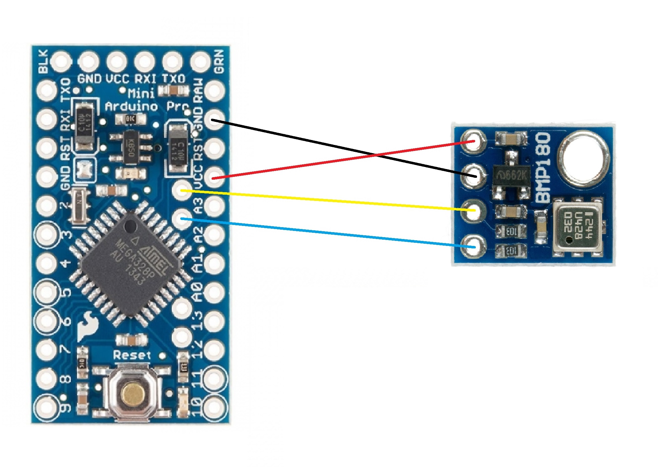
The wiring diagram between the BMP180 and Arduino is well documented elsewhere but I have reproduced one of their images here.
Separate page with Circuit Diagram
The 'trick' I discovered was a method of creating a wiring harness for the Arduino Pro Mini which is polarised (it is impossible to connect it incorrectly without making an obvious visual mistake.) The harness allows the sensor to be 'daisy-chained' with other M-Link sensors as was originally intended by Multiplex. In effect all the sensors connect in parallel, their respective addresses controlling how they respond and insert the data onto the datastream. The harness has two 120 Ohm resistors and a 1N4148 connected to a male and a female JR plug and socket.
The parts list is a follows:
1 BMP180 (5V) HCMODU0101
2 Arduino Pro Mini (5V) HCARDU0059
3 120 Ohm resistor (2 off)
4 1N4148 silicon diode
5 FTDI USB Serial Port Adapter (Optional) HCARDU0011
The circuit diagram shows an address selector which offers 3 sensor addresses: 2, 3, 4. If you omit
that part then the address defaults to 2. You can easily change that address in the programming
environment but the selector allows a jumper system which removes the need for a pc to modify at
the flying field.
The current software is written to the Pro Mini using the standard Arduino programming environment, connecting through one of the many available interfaces. I used the Hobby Components FTDI USB Serial Port Adapter with a carefully modified 6 wire ribbon cable. This is shown in the following document:-
The hardware interface is described in the Multiplex document and is based on the sensor recognising its own digital address and responding by using open collector output to pull down the data input to the multiplex receiver.
The program has two bodge lines where I had to insert a 'special case' to give a correct display of -1 metre.
**************************************************************
Hgt = 32768 + Hgt; // 65536 sets Bit16 so no -1m value
Dum = Hgt + 32768; // Hence adding 32768 twice
**************************************************************
Arduino Code
Separate page with code listing
Home Page
(Latest update 22:August:2019)